
Video Walkthrough
A. Cable Management
Note: Detailed steps regarding cable installation and management will be found throughout the rest of the chapter.
These are our recommendations on how to manage your cables more easily. They don't need to be strictly followed. Don't be afraid to experiment with different configurations.
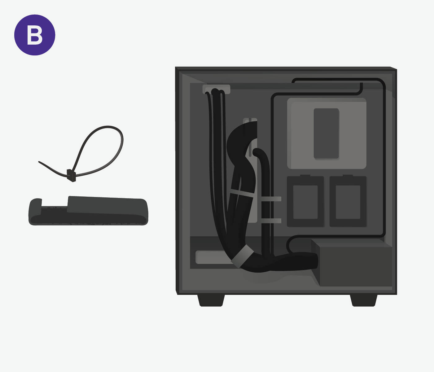
B. Designed to Help
Zip ties and velcro are your friends. For better cable management, we advise grouping cables together and using the provided velcro or zip ties to fasten them to one another.
C. Where To Plug In The Cables
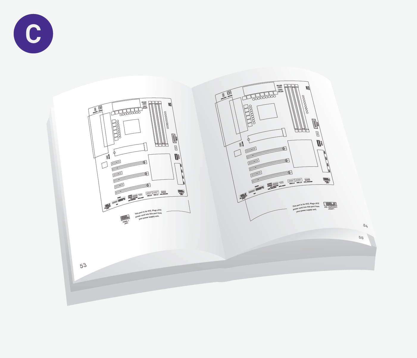
Important: Check your motherboard manual.
Bring out the manual that came with your motherboard. The port names we provide in the upcoming section are commonly used, but they may not be exact. The manual will be very helpful during the upcoming steps in identifying exactly where each cable port is located on your motherboard model.
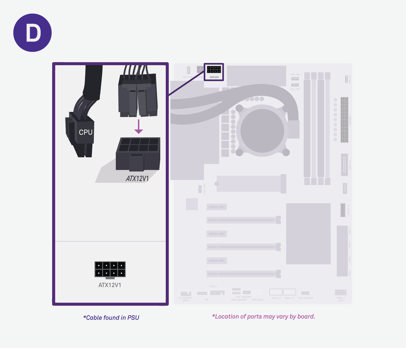
D. CPU Cable
Run the 8-pin cable marked “CPU” from the PSU and plug it into the motherboard. Match the clipping
point on the port to the wire.
*Cable found in PSU.
*Location of ports may vary by board.
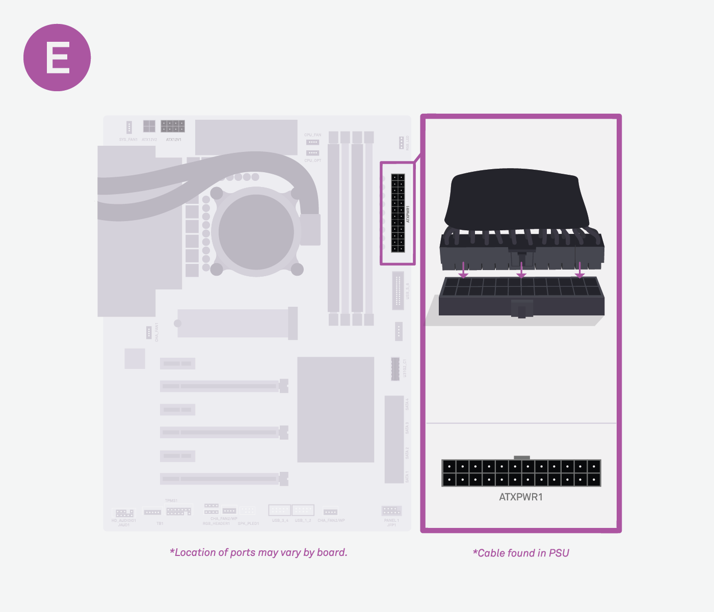
E. 24-Pin Power
Run the 24-pin power to the large ATX_PWR1 port located on the motherboard. Match the clipping point on the port to the wire.
*Location of ports may vary by board.
*Cable found in PSU.
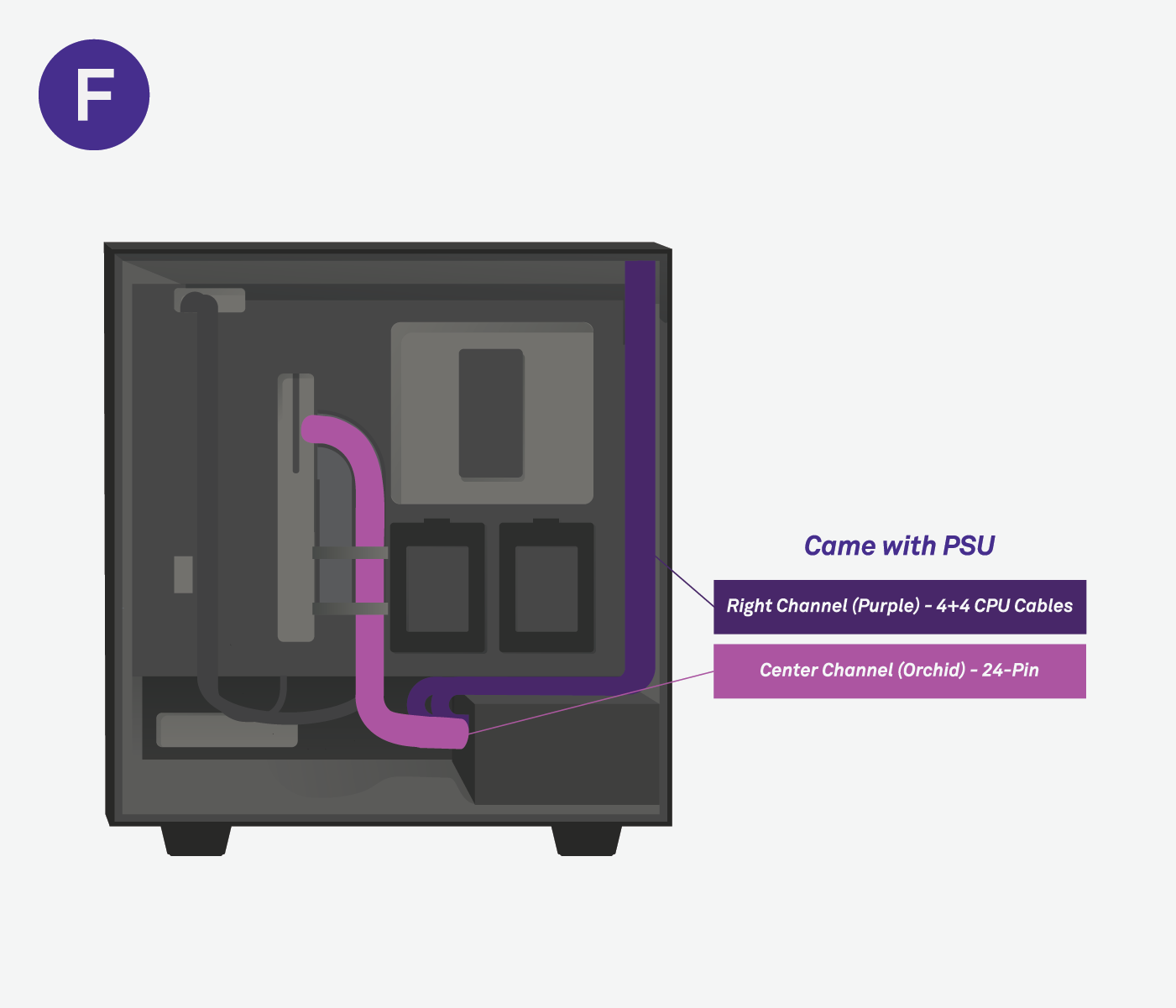
F. Cable Management - 24 Pin & CPU Cable
Both of these cables are found in the PSU. Route the CPU cable along the right-most channel and through one of the top openings, into the CPU port. Run the 24-pin power to the center channel to plug it into the ATX power port.
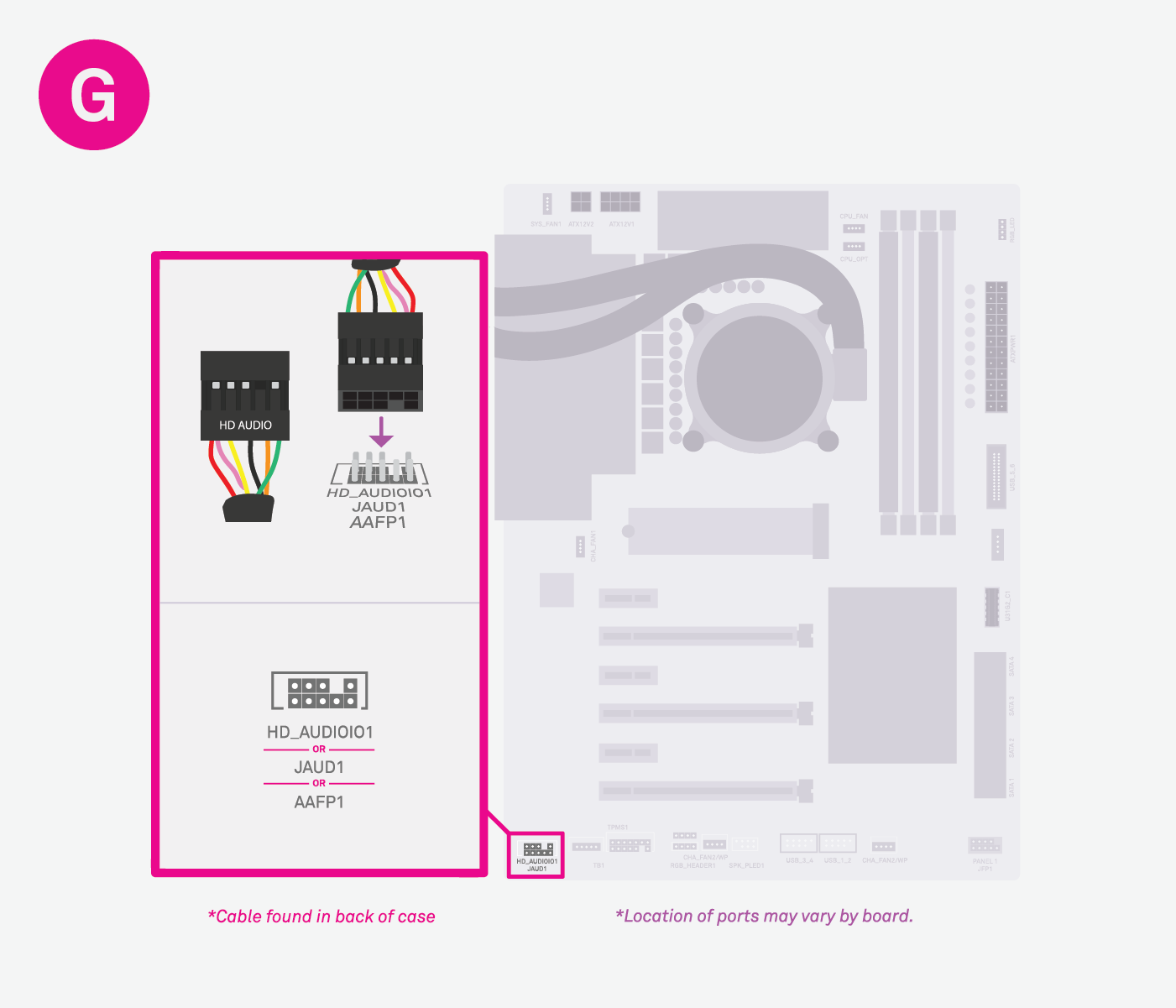
G. HD Audio
Align the plugged hole on the wire with the missing pin on the board.
Run the HD audio cable to the JAUD1/HDAUDIO port.
*Cable found in back of case.
*Location of ports may vary by board.
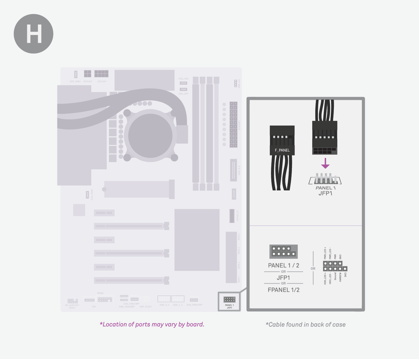
H. F_Panel
Align the plugged hole on the wire with the missing pin on the board.
Run the front panel header cable to the JFP1/PANEL1 port along the bottom of the motherboard.
*Location of ports may vary by board.
*Cable found in back of case.
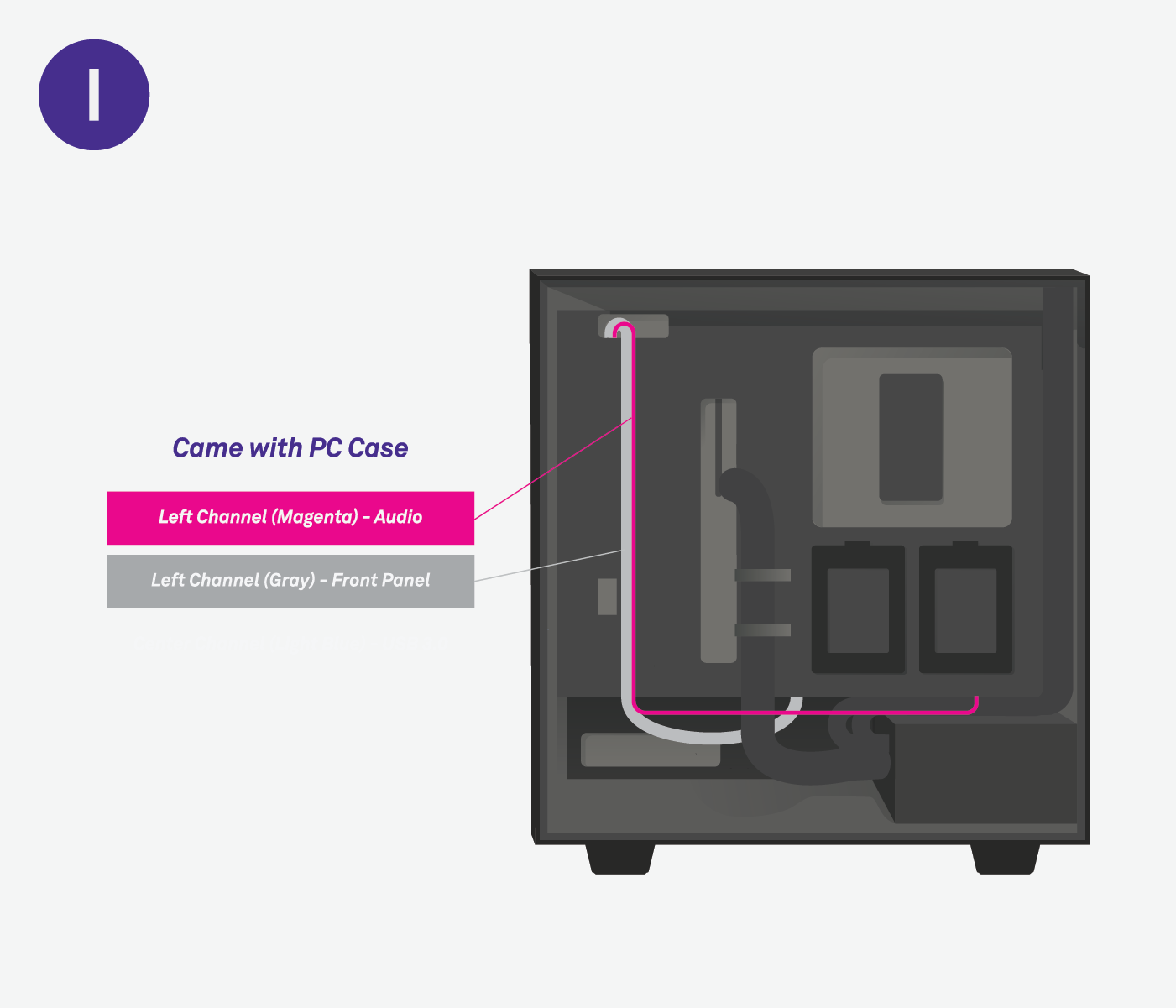
I. Cable Management - Audio & Front Panel
Run both the audio and front panel cables from the left cable channel to the openings at the bottom of the PC case. Both of these cables were included with your case.
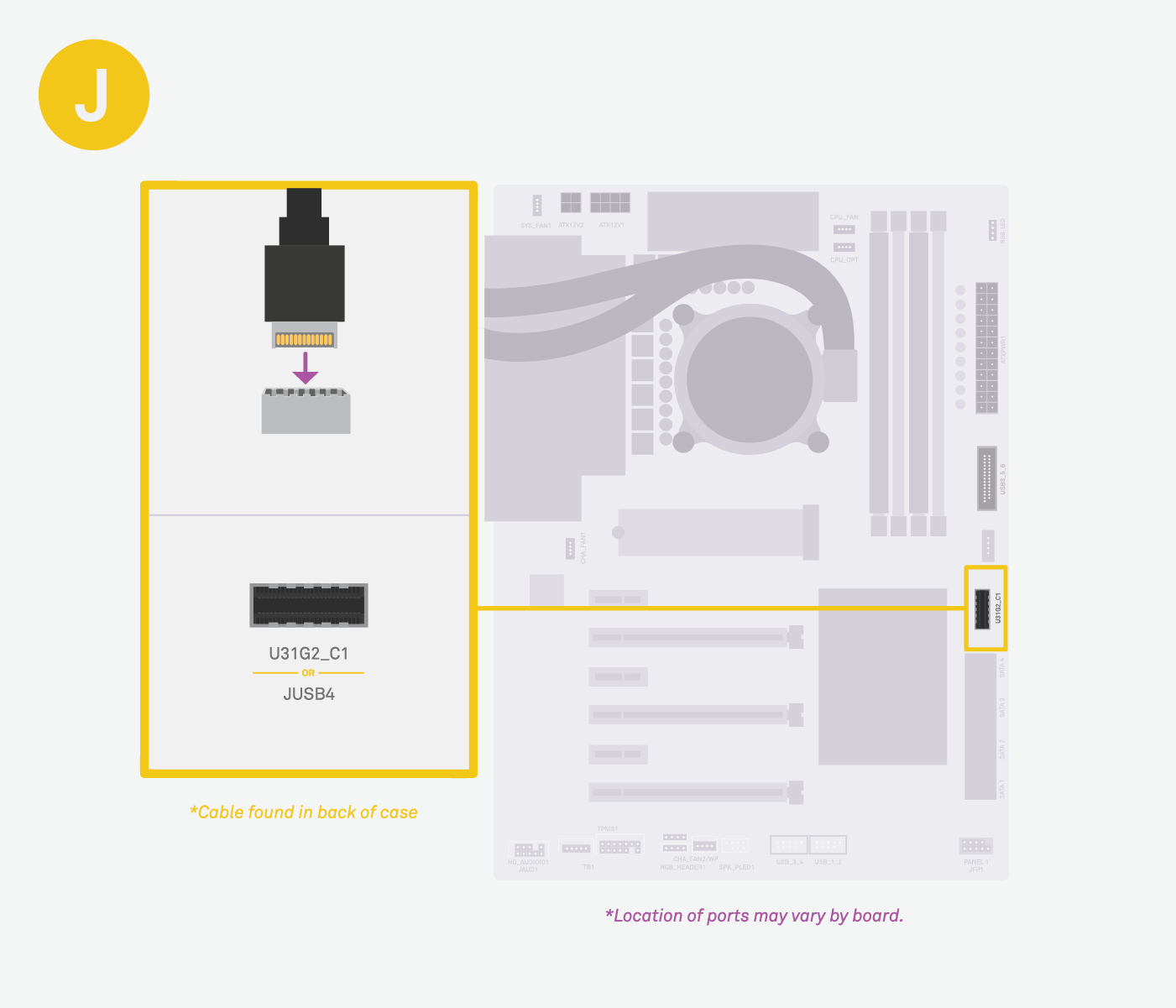
J. USB-C
Your board may not have this port. If so, leave this cable unplugged.
If your board supports USB-C, untie that cable and route it into a U31G2_C1 port.
*Cable found in back of case.
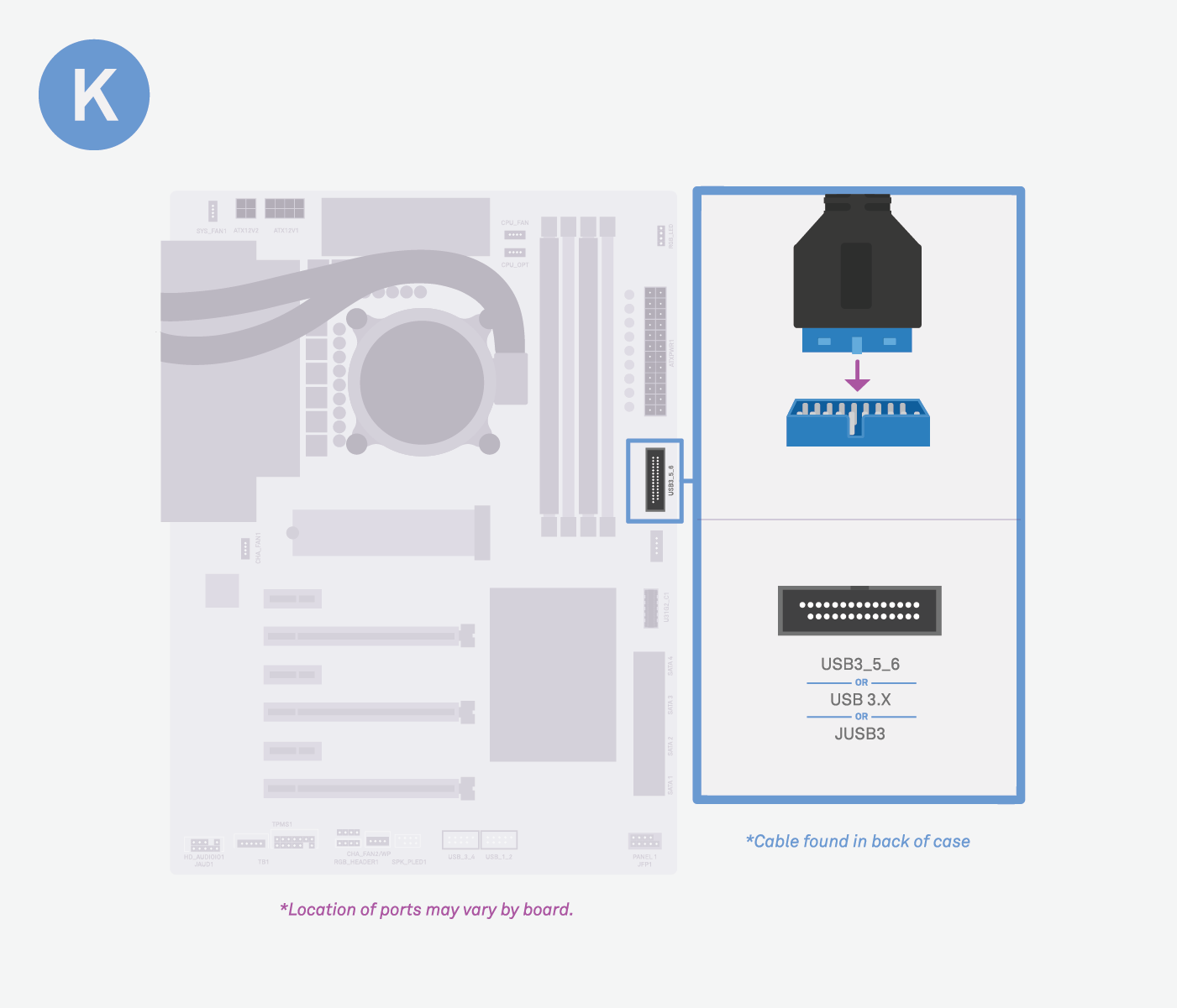
K. USB 3.0
Run the USB 3.0 to the JUSB3 / USB3_5_6 port. Align the nub to the board socket, and plug in.
*Location of ports may vary by board.
*Cable found in back of case.
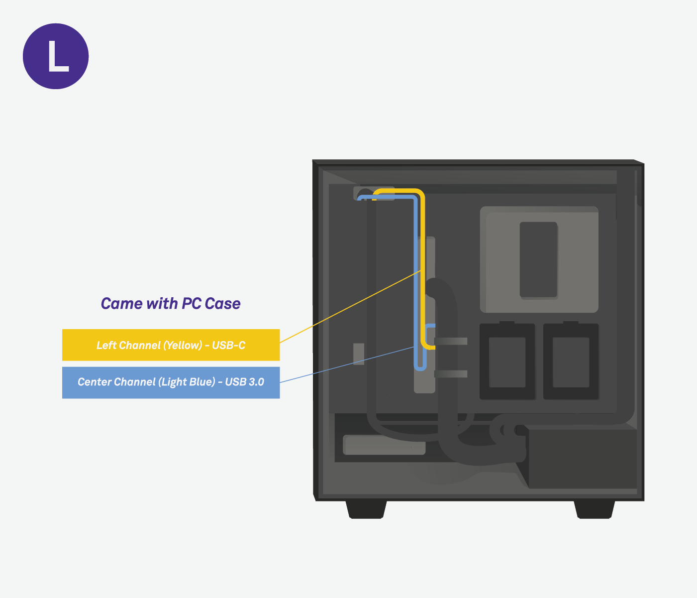
L. Cable Management - USB 3.0 & USB-C
Run the USB 3.0 and USB-C cable from the left channel and through the center channel opening. Both of these cables were included with your case.
M. Fan Cables
Run your two fan cables to any “CHA_FAN” or “SYS_FAN” 4-pin port on your board. The case fan cables will have 3 holes, so make sure that the clip aligns with the port on the board.
*Cables found in back of case.
*Location of ports may vary by board.
N. Cable Management - System Fan Cables
Important: AIO builds (labeled E) will not plug in any cables (fan or radiator) from the top-front PC bracket at this stage.
Run the system fan 1 cable along the left channel into one of the bottom openings. Then, run the system fan 2 cable through the right channel into one of the bottom openings.
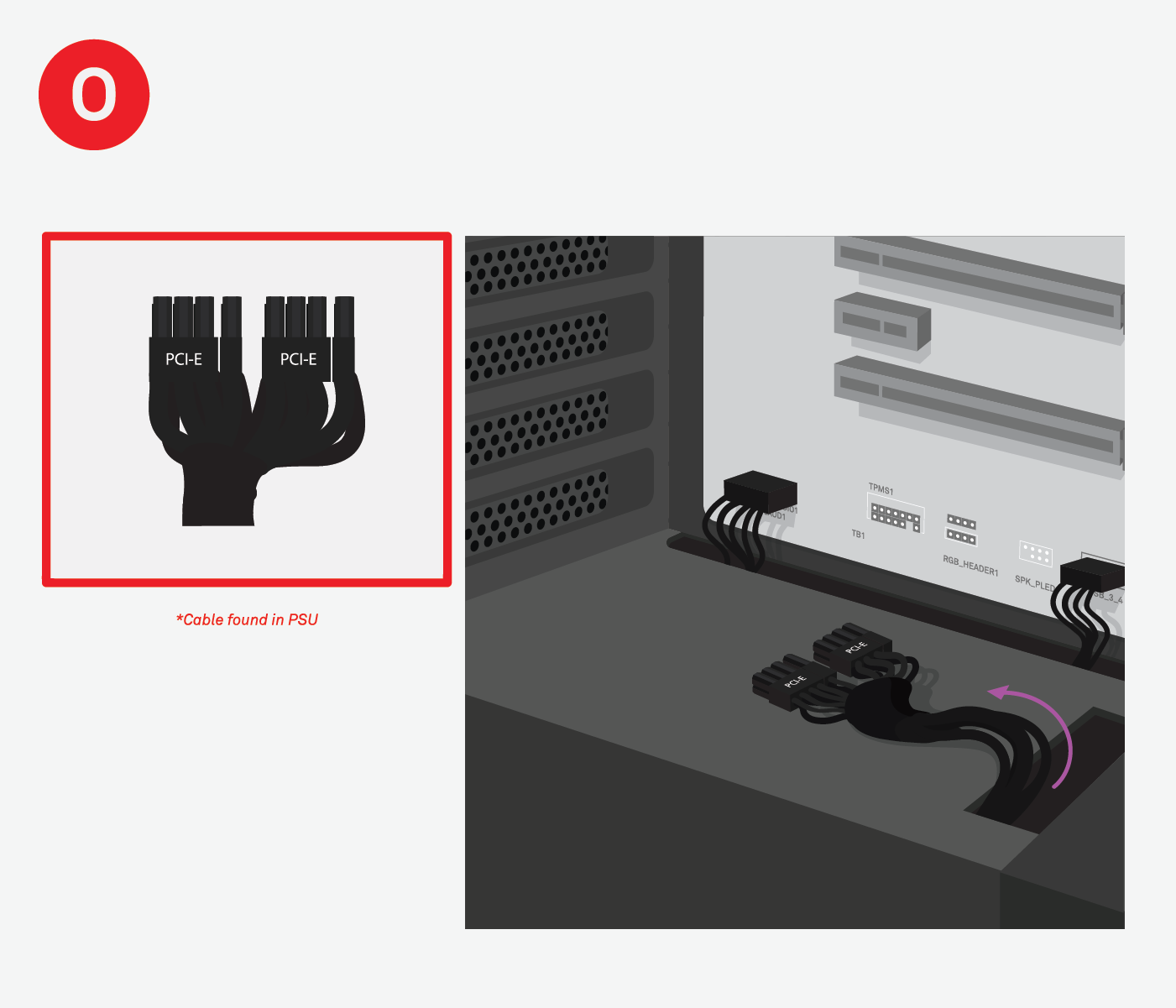
O. Prepare the PCI-E / VGA Cable
Run the PCI-E / VGA cable(s) through the hole in the metal panel between the PSU and the inside of the case. This metal panel is called a PSU shroud. Do not plug in yet. Leave these cables for when we install the GPU in a later step.
*Cable found in PSU.

P. Cable Management - PCI-E / VGA Cable
Run the cable(s) labeled PCI-E or VGA from the PSU directly up through the PSU shroud (metal panel separating the PSU from the motherboard). This cable came with your PSU.

Online Tech Chatnzxt.com/support |
Call Center1 (844) 791-1341 |
Comments
0 comments
Please sign in to leave a comment.